Predictive Simulation to Virtually Test Product Design and Reduce Time to Market by Trinseo
With technical progress and new regulations, shorter product cycles are a continuous challenge for OEMs. Modelling is one measure to cut time to market efficiently without compromising product quality. Trinseo Technical Service & Development specialists Kersten Terry and Berend Hoek explain the process of computer-based simulation, specifically applied to injection molded plastic parts. Through case studies, they showcase how Trinseo’s Application Engineering Development resource facilitates more effective LED-lighting development relative to part design, tool design and material selection by modelling “real world“ performance.
LED lighting offers the lighting industry several advantages including increased energy efficiency, durability and design flexibility. In addition, as regulations, consumer demands and material expectations evolve, OEMs are rushing to introduce more and more innovative and sophisticated lighting units to create and maintain a competitive advantage. To determine the most effective and efficient way to leverage the various design possibilities for LED lighting and to deliver on complex demands, manufacturers are using advanced development methods to design lighting components, which, at an increasing rate, are being made of plastic.
Computer-based simulation technology, also known as Virtual Prototyping, offers developers a cost-efficient approach to designing the exact application they need without wasting time, materials or production effort on an approach that could produce unsuccessful results. It allows manufacturers to ensure that their end-applications will address design and functionality needs and meet project specifications prior to production. The upfront work done using this method ultimately results in shorter-to-market development time and reduced tooling cost, which for an OEM is a significant benefit. Without simulation analysis, OEMs are often unable to identify design and functionality defects before they occur, which can lead to issues such as flawed light diffusion, uneven surfaces, inaccurate haze levels and poor mechanical properties in the final product. Encountering these issues late in the development process, or once production is about to begin, costs manufacturers time and money as they must not only determine the root cause of the defect and the solution for preventing it, but also modify the development process itself, which can include having to redesign a tool or make investments in alternative materials.
Computer-Based Simulation: How and When It Works Best
Computer Aided Engineering (CAE) technologies are not only used to model fabrication processes but also to predict how end-products will look and final assemblies will function. One of the most effective of these methods is Computer Aided Design (CAD), where software is used to create a digital prototype of an injection molded plastic part or assembly and demonstrate “on the screen” its functional and in-use characteristics. By digitally simulating an application and the processes it must undergo, developers and manufacturers gain critical insight into not only its aesthetics and functionality but also how each element involved with producing the application - ranging from upfront design of the tooling to the material used - will impact the overall performance of the end-product.
Many OEMs conduct their own computer simulations focusing on an application’s functionality. However, creating digital replicas without specifically targeting the material used in the fabricationprocess prevents manufacturers from envisioning a key foundational element of the application and its manufacturing process, potentially resulting in a less than satisfactory end result and costly re-development efforts. Involving material suppliers in a simulation may be beneficial and could provide a more holistic view of an application development process, because the material supplier offers a more in-depth understanding of the materials used and their potential behavior during processing. In turn, a material supplier’s simulation can help OEMs reduce the risks in an overall production process, eliminating costly trial-and-error when developing a physical product. This ultimately helps companies bring new and better concepts to market faster.
To develop a computer-based model, a close collaboration with customers is very important. OEMs approach the development team for one of two reasons:
• Guidance on planned injection molded plastic parts with specific performance or design requirements or
• Advice on already-developed applications with issues / concerns that need to be addressed
The application engineering development specialists then work with OEMs to create brand new or modify existing designs by using various CAE simulation processes based on material-specific properties, the OEM’s geometric definition of the part, and any requirements imposed on the end-product, e.g., impact, optical, UL regulatory, etc. Using this information in simulations, developers can predict the mechanical behavior of the part and recommend further optimization. They can also create virtual prototypes using desired material specifications that can solve an existing design or functionality issue, observing flow and mechanical properties in an injection molded part. Once the prototypes are created, the OEM can produce the end-product with increased confidence in the final result.
Computer-based simulation can be beneficial at any point of an OEM’s development process, whether upfront when creating a new injection molded part or “at the back-end” when troubleshooting issues that may surface in an existing part or when optimization is needed. It is most cost-effective however when CAE is used before production begins, similar to developing a Failure Modes Effect Analysis (FMEA) in the production world, as a means to anticipate and then prevent potential failures.
A typical development process for LED lighting includes different phases from planning to actual application production (Figure 1). During the planning stage of development, ideas are sketched out, perhaps on just a note pad. During product design & development, CAD files are developed for the molds to create the plastic parts and perhaps prototype tooling is built. During process design & development, the manufacturing phase is tested out, and process parameters in the molding process are identified. For plastic injection molding, pressures, temperatures, speeds are determined to produce plastic parts. Next, the product and processes performance requirements are checked during the product & process validation phase. Finally, the application goes into production.
When involved upfront in the development process, material suppliers can help OEMs achieve their goals by foreseeing trouble areas ahead of time and developing a specific material grade needed to create an optimal LED-lighting part. While it is most common to use computer-simulation to intervene during either the process design & development or the product & process validation phases as indicated by figure 1, it is also possible to involve simulation studies at earlier stages in the process such as in the planning or product development & design phases.

Figure 1: Development phases involved in designing and manufacturing LED components
As seen in figure 2, the point within the development process at which OEMs choose to digitally produce end-products has a direct impact on related production costs. Computer-based simulation reduces potential financial risks at an increasing rate as project lead time increases. The longer a company waits to use computer-simulation, the more costly the repercussions can be. For example, if an OEM introduces simulation during the tooling design phase, it can avoid costly changes that would likely be encountered after an investment has been made, the tooling has been built, and/or production has started. Modifications to an existing tool design or an investment in brand new tooling may be prohibitive. Similarly, the more technical and complex an end application (assuming cost also increases) the more the development and production process will benefit from computer-based simulation early in the design phase.
 Figure 2: Correlation of Cost of Change vs. Time indicating a steep increase in cost as development progresses
Application Development Engineering was first introduced by Trinseo to customers in its automotive business, where it is typical for a material supplier to be involved in the design phase of injection molded plastic automotive parts. In one of its first computer-simulation partnerships, through extensive research and development, it was possible to gain an understanding of the effect of adding Long Glass Fibers (LGF) to a polymer and how processing methods affected the performance of the final part. Long glass fibers are used to enhance the mechanical properties of thermoplastics which then can be used for applications to reduce weight or even replace traditional heavier materials such as steel. With its simulation expertise, it was possible to develop applications meeting the desired level of mechanical performance required by the customer without having to rely on trial and error and without going through multiple prototype phases.
This methodology of simulation can be used much the same way in LED Lighting. With its complex needs for intricate part design and increasingly strict market regulations for safety and efficiency performance the LED lighting industry potentially has much to gain. Computer-based simulation gives OEMs virtual control over a wide array of design and material considerations necessary to create an injection molded part while allowing them to avoid the costs of trial and error, i.e., trying multiple options in real-life production not really knowing the outcome. Additionally, as plastic materials are used more and more regularly for the components of LED devices, CAE technology becomes even more advantageous to manufacturers, allowing them to test different polymeric solutions to achieve the right material-property balance for an optimal end-product in design and functionality.
Computer Aided Engineering (CAE) Studies: Where to Begin To conduct a CAE study, an application development engineer requires the following:
• A CAD drawing of the plastic part that needs to be injection molded
• Polymer characteristics such as viscosity vs. temperature and shear rate data, melt mass flow rate, thermal conductivity, specific heat, pressure-volume-temperature
• Processing parameters used or anticipated by the injection molder, e.g., temperatures, speeds or pressure
• Desired performance description, e.g., no weld lines or drop testing mechanical performance
• Description and/or actual parts demonstrating the issue or concern
• CAE software for conducting process- and/or mechanical simulations
Using this information the engineer can run simulations to predict how the material will enter a mold and where potential defects may occur. They can predict weaker areas that might be susceptible to breaking due to being a high stress area.
Using this approach, the following case studies show how CAE may be applied to enhance or optimize designs for injection molded plastic components used in lighting.
Case Study: Meeting Mechanical Design Requirements
One of the most significant benefits of LED lighting is the freedom of design it affords, where designers and manufacturers are able to offer end-customers specialized shapes for their lighting applications for specific functionality and aesthetic needs. The desired form and function of the lighting should dictate the development process starting at the time of project planning. If the part is designed without considering performance standards, manufacturers can encounter issues that could potentially cost them both time and money in adjustments that must be made “after the fact.”
To help one of the customers avoid such a situation in its development of a new product, the development engineers used computer-based simulation to highlight a specific area of a plastic injection molded light fixture. The OEM needed to ensure the strength of the end product, making sure it could endure impact without breaking. The developers used simulation to predict the optimal product design that would achieve this desired mechanical performance.
To approach this project, a “Drop- Test” study was simulated where a virtual prototype of the final part was created via computer-aided design. Different impact scenario’s were simulated that were equivalent to those associated with the part falling onto a concrete floor and analyzed the behavior of the prototype. That helped to pin-point the weakest and most vulnerable areas of the part. As seen in figure 3, the area is most susceptible to breakage were the connections protruding from the base of the application.

Figure 3: Drop-test simulation for identifying the weak point in a product prototype and suggested improvement using a rib
After determining the most vulnerable areas of the application, the developers were able to identify solutions to support these areas of the part design. In this instance, it was suggested to add reinforcement ribs near the weak connection in order to strengthen the part overall. Given that the simulations were done during the process & development phase, the OEM was able to incorporate these suggestions into the tool design that would be used for molding the part and therefore avoid expensive modifications that would have been needed if the part had been produced without first conducting the simulation of the drop-test.
Case Study: Choosing the Right Material
As the lighting market requires more performance properties from its devices - including cost savings, energy efficiency, and light-weight parts - the material used to produce the LED parts plays a critical role. Given their ability to be custom tailored, plastics, such as polycarbonate and polycarbonate blends, enable a manufacturer to reach stringent part performance requirements.
To meet the desired form and functionality of an application, while keeping production costs low, OEMs can use computer-based simulation. The virtual prototypes help developers foresee how a material will react throughout processing and visualize any potential defects or performance failures in an end application, therefore helping to determine the right material to be used to avoid any issues. If implemented after the fabrication process, these defects will not appear until the product is already cast in a final shape, causing OEMs to scrap defective parts, choose a new material and re-fabricate an application. This of course represents another costly error.
In a related instance, a customer had observed light deflection in one of its plastic, injection molded lenses. To determine the cause of the issue, the developers combined their extensive material knowledge with CAE tools to digitally recreate the lens and simulate the process of filling its mold with two different material options.
The simulations showed that the materials behaved differently relative to filling pressure, filling pattern and cooling sequence. Through this comparison, developers were able to see that the viscosity of each material directly affected how the material performed during each of these phases and resulted in different shrinkage levels at the end of the production process. The more shrinkage, the more the lens’s shape and size was distorted, therefore causing unwanted light deflection.
 Figure 4: Comparison of calculated deflection of two materials
In the final phase of analysis, the developers could easily see the distinction between the two grades of plastic. Material 1, with a higher required filling pressure also resulted in a higher shrinkage and possessed a deflection of approximately 2 times higher than that of Material 2. Material 2 displayed less shrinkage during the simulation (Figure 4). As a result of the computer-based simulation of this production process, it was possible to confirm that the issue could be prevented through the correct choice of material. As a consequence, the optimal polymer grade for avoiding shrinkage and the subsequent deflected light in the end-product was suggested (which would be more uniform, in the case for Material 2).
Case Study: Determining the Proper Mold Filling Process
To translate an application design that is specially developed to meet specific performance and aesthetic requirements into a viable production process, OEMs must create tooling or molds that not only meet required specifications but, at the same time, ensure consistency of each part or component. Creating these tools involves considering the application’s specifications and accounting for how the chosen material will behave within the tool during the fabrication process. Even after taking necessary precautions, manufacturers may still be confronted with unexpected problem areas in a final molded product, including aesthetic defects such as visible weld-lines (a small line appearing on the surface of the application, created by two flow-fronts joining each other) and potentially inconsistent coloring.
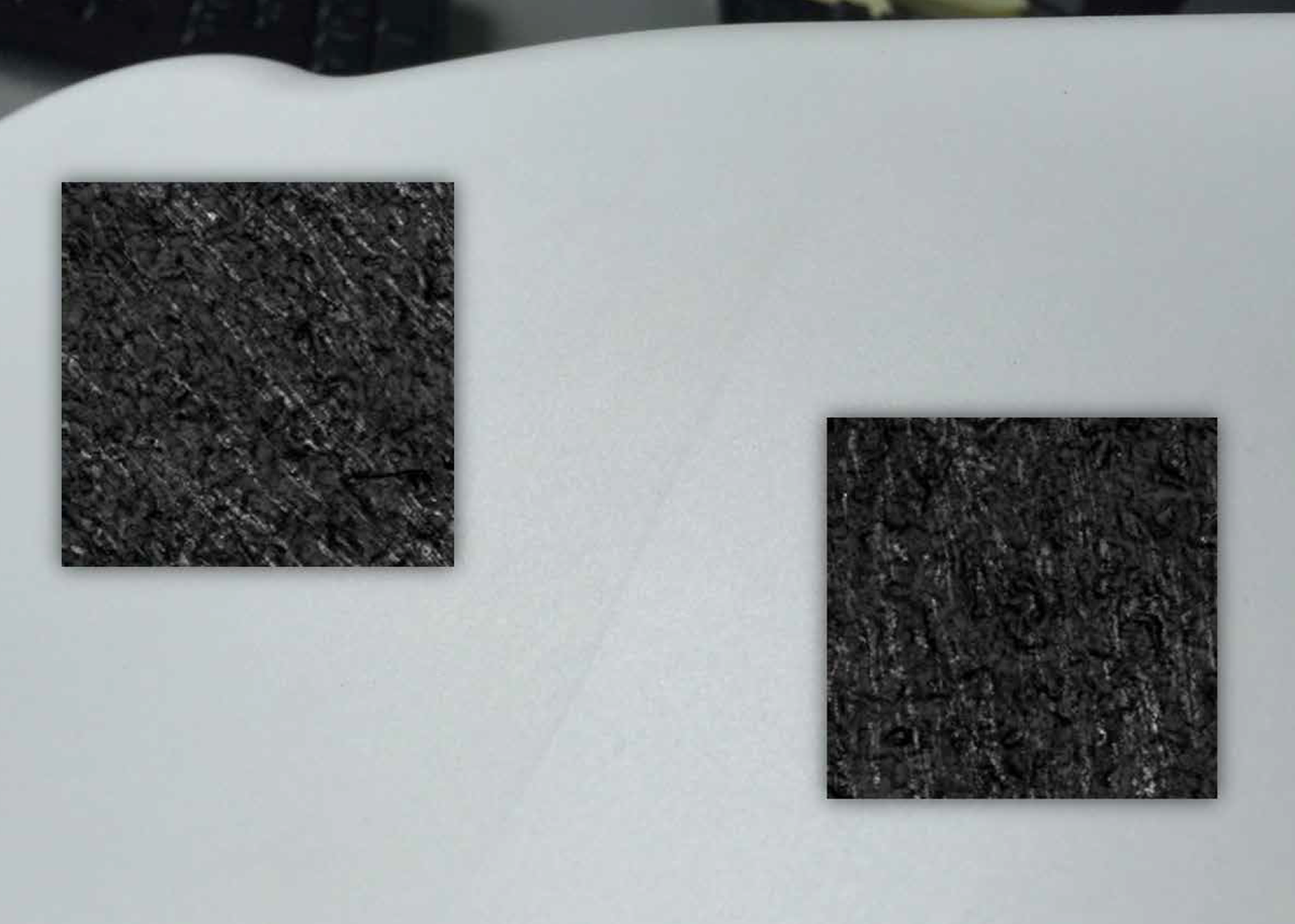
 Figure 5: 3D surface scan showing fiber orientation of material – inset images - on both sides of the visible weld-line on the end-product
A customer encountered such an issue after the mold was created and production began. The customer noticed areas of unwanted grey streaks near the weld-line on its final molded product. The OEM originally concluded that the defect was due to material degradation, but after conducting a 3D part surface scan simulation (Figure 5), the developers saw that the glass fiber orientation varied on both sides of the weld-line, causing the light to deflect differently in these areas and create the illusion of lighter- and darker colored zones. The team used computer-based simulation to observe precisely how the mold was being filled during manufacturing and ultimately to pinpoint how the defect was occurring in the end-application.
The design engineer simulated the mold-filling process, comparing various mold-filling sequence options, including when each gate - the opening where the material is injected into the mold - is used during the filling process. The mold filling simulation software is used to identify how the polymer flow front is filling the tool cavity. The flow front in an injection molding process is the position of the molten plastic in the empty mold cavity. In the simulation images below, the filling process and the alternative ways of part filling are mapped and displayed through color coding where red represents locations in which filling first begins at time zero seconds, and dark blue represents the final filled areas, after five to six seconds (Figure 6). This information allowed the team to determine how and where in the part the material creates weld-lines.

Figure 6: The image on the left shows weld line formation, the image on the right shows a gating scenario which avoided the weld-line
In this particular example, the mold originally employed five different gates where the material was injected into the mold. The material’s behavior was simulated, varying the filling sequence. By changing the sequence in which the gates fill the mold the figures show the locations of where the polymer last fills the mold.
Comparing the different gate filling sequence, the developers identified a strong correlation between the regions showing the surface defects and the temperature of the material in these same areas. This difference in temperature was caused by the rate of material injection, pressure and, ultimately, cooling time. In turn, overcoming this temperature difference contributed to a more inconsistent texture reproduction throughout the part. From these results, it was concluded that the filling sequence should be altered to create a more uniform flow front temperature throughout the material, requiring a reduction of the gates used in the mold. Reducing the number of gates from five to three resulted in fewer weld-lines, more homogeneous temperature and a much more well-balanced filling pattern for the part overall.
Case Study: Evaluating Alternative Solutions
As LED assemblies become more and more complex, so too are the processes and materials used to manufacture them. Each step of the production process offers several opportunities for modifying and improving the final end-product, including multiple variations within the part design, tool design and material selection as discussed in the previous case studies. Often computer-based simulation will identify for OEMs potential causes of issues in end applications and even possible solutions for eliminating those issues. At such a point, the task includes determining the optimal solution among the choices presented to best produce the application not only according to performance demands and requirements but also aligned with the company’s budget and timing needs. Using advanced production analysis and considering options, companies are able to test solutions and compare their end results, helping them to envision the best modifications to make in their production processes.
In one such situation, a customer faced a problem in its production process, resulting in an optical defect in an injection molded plastic part. This application displayed highly visible weld-lines at the point two sections joined one another (Figure 7). As the part design, tool design and material selection were already in use in production, the project required an in-depth analysis to pinpoint the cause and identify the optimal solution. Using process simulation, a so-called virtual “Short-Shot” study was created, which is a technique to help molders see more precisely how the mold is filled and the resulting part is formed.

Figure 7: Visible weld lines present an optical defect in the end product
From this benchmark simulation, it was observed that the optical defect was formed at the end of the filling process, as shown in the image on the left in figure 8. (In this figure the blue areas represent mold sections that are filled first by material injection and red areas represent those filled later). Further analysis showed that the cause was related to the filling speed and direction of different material areas during injection, where the horizontal flow-front of one material section overtook the vertical flow-front of another material section that was moving upwards to join the gap during the filling sequence.

Figure 8: Left image shows filling pattern leading to an optical defect while the image on the right shows a smoother filling pattern, thereby overcoming the weld-line
The developers then conducted further simulations to identify feasible alternatives for avoiding this problematic “crash” of flow-fronts and to smooth out the filling pattern in order to eliminate the weld-lines in the end-product. After simulating several options to modify the part, such as altering the thickness of the part’s side walls, bottom, and front edges, the team discovered two potential solutions offering a similar improved result.
The identified solutions included:
• Option 1: modify the tool design, introducing an additional injection gate in the mold, and
• Option 2: change the material used for the application.
As seen in the image on the right in Figure 8, both solutions provided a more well-balanced filling pattern when compared to the original process. Either changing the tool design or changing the selected material would create a smoother flow-front of the injected material at the point of connection during the filling process and thereby facilitating a less visible joint, i.e. a cleaner connection between the two flow-fronts. This ultimately would eliminate the optical defect in the end-product.
With a deeper understanding of the optical defect’s cause and its potential solutions, the OEM was able to make an informed decision, identifying the solution that best aligned with its existing production budget and timeline. Computer-based simulation offered the OEM the flexibility and confidence to choose the optimal solution for its final injection molding process without sacrificing the desired end-product performance or internal manufacturing objectives.
Conclusion: A Clear View Through Computer- Based Simulation
OEMs in the LED industry are no longer forced to wait until a production process is complete to fully assess their applications. Now with computer-based simulation, manufacturers can have a comprehensive view of an end-product’s performance before investing time or money in the part design, tooling, material selection, or production. Through these virtual simulations, OEMs are able to visualize each factor that affects the application, from the behavior of material within a specific tool design to the precise sequence used during the injection molding manufacturing process to how a product’s form can influence its ability to function in various situations. Equipped with this information, manufacturers can be fully confident in their development decisions and move forward in their production processes without the risk of increased spending due to errors in design.
CAE technology is a proven methodology for anticipating molding performance and end product properties and with the added expertise of the plastics material supplier, computer-based simulations offer an accurate picture of a product to avoid potential design and performance issues and resolve any existing problems. In close collaboration with customers in the LED Lighting market, these simulations have helped solve issues that other material production partners could not resolve and even assisted in the creation of new product concepts that would have otherwise not been able to be launched.
While the LED Lighting market continues to grow, the challenges presented to OEMs increase. The sooner in their processes that these companies implement computer-based simulations, the more quickly and efficiently they can create products that will effectively serve the needs of the industry and offer opportunities to save time and money.
