Direct Current (DC) Supply Grids for LED Lighting
Since many alternative energy sources as well as electronics and controls technologies are based on DC current, DC grids have been investigated more intensely in the last decade. DC grids with a centralized AC/DC conversion have proven to be advantageous in server farms. While LED lighting is also a DC current related technology, an obvious choice would be to use DC grids for them. Prof. Eberhard Waffenschmidt from the Cologne University of Applied Science in conjunction with Philips Research presents the results of an office building DC lamp system installation with photovoltaic (PV) support.
Abstract
Most electrical devices operate on direct current (DC) internally, but are supplied by alternating current (AC). A power supply with DC makes the rectifier electronics unnecessary. This makes the devices simpler and more reliable and generates less power losses. Especially, if many identical devices like lamps in supermarkets or open offices are operated, this becomes evident.
This publication aims to show solutions of DC operated professional buildings like offices or supermarkets and homes. A special focus is put on high voltage supply at 380 Vdc. First, the component effort for solutions with AC and DC current supply are compared. Especially LED-lamps can benefit from a DC supply, because lamp drivers can be reduced to a few reliable components. Then, a loss breakdown including transmission losses is presented. The major advantage of a DC supply appears, if a micro- grid including decentralized energy generation and storage is considered. In addition, standardization initiatives working on high voltage DC grids are listed. Finally, a realized office test bed including DC light emitting diode (LED) illumination and photovoltaic (PV) support is presented.
Introduction
One trend in lighting is to distribute light sources. This becomes possible with LED lamps, which offer a small amount but efficient light power. However, this also requires efficient lamp drivers. Furthermore, assigning each lamp its individual lamp driver becomes a high effort in material. Therefore, concepts are needed to deal with an increased number of similar lamp drivers. One solution could be to use a DC power supply. This makes omission of the rectifier electronics possible, which, in turn, makes the devices simpler, more reliable and generates less power losses. This is attractive especially in installations where a high number of lamps are connected to a power rail, like in open space offices or supermarkets (Figure 1). Each lamp contains an AC to DC conversion circuit, which can be omitted with a DC supply rail. This becomes particularly attractive if the system is combined with a local photovoltaic generator, as shown in [1].
DC supply systems are proposed by a number of publications especially for residential applications, e.g. [2] [3]. But as derived in [4], a large variety of different requirements for different devices, a DC system for residential applications faces even larger challenges. Contrarily, in lighting applications the loads are quite similar in their requirements and thus much better suited for a common DC supply.
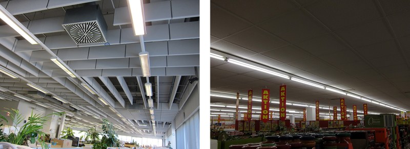 Figure 1: Lamp installations in open office space (left) and supermarkets(right)
Effort for AC to DC Conversion
Figure 2 shows the block diagram of a typical lamp driver operated on AC with the parts necessary for AC to DC conversion. Similar components are necessary for all AC power supplies.
The rectifier is the essential element and is typically a bridge rectifier consisting of four diodes. The electrolytic capacitor (elcap) levels out the pulsating rectified sinusoidal voltage. Recently IEC SC77A WG1 agreed to a new review of the standard IEC 61000-3-2, which means that in the near future lamp drivers with more than 5 W will require a power factor correction (PFC) circuit. A PFC ensures that the current drawn from the grid is sinusoidal. The PFC may consist of an inductor, but this is usually too bulky. Especially for higher power levels a switch mode converter, typically a step up converter (boost converter) is used. However, this requires a filter to avoid higher frequency content generated by the switched mode PFC polluting the grid.
Space and components saving
Figure 3 shows a photograph of a Philips Xitanium lamp driver for a 39 W light emitting diode (LED) lamp as used in the reference setup. In the figure, all parts that are necessary for AC to DC conversion, are marked. As can be seen, approximately 40% of the printed circuit board (PCB) is occupied by these components. Especially the PFC and the filter circuit require a lot of space. The storage elcap is also significant, but the bridge rectifier itself is a comparable small component.
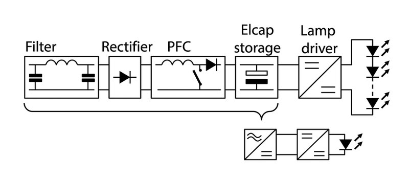 Figure 2: Typical AC lamp driver
 Figure 3: Power driver for a 35 W LED lamp
|
Component |
AC supply |
DC wide voltage range |
DC narrow voltage range, mechanical rev. polarity protection |
|
Filter |
Required because of PFC |
Required because of DC-DC |
Can be omitted with linear driver |
|
Rectifier |
Required |
Required for reverse polarity |
Omitted |
|
Power factor correction (PFC) / DC-DC converter |
Required |
Required to match wide voltage range |
Not necessary |
|
Elcap storage |
Required to avoid flickering |
Required because of dips |
Can be omitted, if dips are accepted |
Table 1: Overview of required components for AC to DC conversion
As discussed, these components might also be necessary for DC operation. An overview of this is shown in table 1. The bridge rectifier may be necessary to allow an arbitrary connection of the DC supply leads. However, this problem may also be solved by a suitable mechanical coding of the plug to avoid a wrong connection. The elcap may be needed to suppress voltage dips of the DC supply. However, it should be acceptable for lamps to pass the dips to the lamp and allow a short flicker. Then an elcap is not necessary.

Figure 4: Power and loss characteristic of a linear current controlled LED driver
If the DC supply voltage has a large variation, it may be necessary to convert it to a constant level of an intermediate voltage. This requires a DC-to-DC converter, similar to an active PFC. However, if the DC voltage range has a narrow specification the DC-to-DC converter can be omitted.

Figure 5: Loss comparison of AC grid (a) and DC grid (b)
The filter is necessary to suppress high frequency contents of switched mode converters. It becomes necessary if an active PFC is used. If the lamp driver itself uses switched mode conversion, it remains necessary. However, with a linear lamp driver, even the filter may be omitted.
In conclusion, the components needed for AC to DC conversion can be omitted if the DC power plug is mechanically coded, if dips can be accepted, if the voltage is specified in a narrow range and, optionally, if a linear lamp driver is used.
Linear LED driver
The advantage of a lighting DC supply becomes most obvious with LED lamps. A most simple “driver” for an LED is simply a resistor. If the supply voltage is very well defined, this would be the most simple, reliable and durable “lamp driver”. However, if the voltage is less stable, the brightness of the LED would vary remarkably, because a small voltage variation would already lead to big changes of the output power.
A solution, nearly as simple, is a linear current driver. A linear current source can easily be built with one J-FET and one resistor. The efficiency of such a circuit is good and is calculated assuming a constant forward voltage Ud of the LED and neglecting a residual voltage drop at the FET. The results are presented in figure 4. As long as the DC supply voltage Us is larger than the forward voltage Ud, the LED power (blue) is the nominal value. If the supply voltage increases above Ud, the voltage across the FET rises linearly. The power loss in the FET (orange) increases proportionally to it. Efficiency (yellow) is calculated from the LED power and the losses.

Figure 6: Loss comparison of AC grid (a) and DC grid (b) with photovoltaic and battery storage operation
If the voltage variation is within ±10% of the nominal voltage UN (like in the public AC grid), efficiency can still be above 84%. This simple and reliable circuit can thus achieve similar efficiency to small-switched mode converters, as long as the voltage range is narrow enough.
Loss savings
The components needed for AC to DC conversion also generate losses. Typically, the smaller the device, the lower the efficiency. Our own measurements showed losses in the order of 5% of the output power for lamp drivers. This arrangement is shown in figure 5a. These losses can be avoided if the device is operated on DC. But if the AC grid supplies the DC grid, an additional central rectifier is needed. However, this central rectifier can be more efficient due to its larger size.
Its losses are estimated at about 2% of its output power, as illustrated in figure 5b. In addition, cable losses can be reduced if a DC voltage of 380 V is used, as shown in figure 7. In total, losses of about 5% of the output power could be avoided using a 380 V DC grid.
Even larger loss savings can be achieved in a different use case as illustrated in figure 6. It shows a system that is optimized for self-consumption of photovoltaic (PV) energy. The PV energy harvested during the day is stored in battery storage and used in the evening.
If all components are connected to the AC grid, losses in the AC to DC (and vice versa) converters end up to be 10% to 13% of the output power (Figure 6a). In a DC system, these losses can be completely avoided (Figure 7b). Reference [5] shows a similar result for such a system, where operation including PV and battery is considered.
Voltage Selection
The supply voltage of the DC grid also has an influence on the losses. Low voltages like 24 V or 48 V have the advantage of being safe to touch and commercially available devices exist. However, to transmit the same power, much higher current I is necessary compared to 230 V AC. A high DC voltage like 380 V is compatible to many 230 V AC devices, which operate on a similar intermediate DC voltage internally.
The power loss Ploss in the cable is proportional to the square of the current
I: Ploss ~ I2. Figure 7 shows the cable losses that appear at different supply voltages, scaled to the losses at 230 V AC. To achieve the same losses at higher currents, the cable cross sectional area A must also be scaled proportionately to the current: A ~ I2. Therefore, the same figure 7 shows the amount of copper that is necessary to achieve the same losses as with the 230 V AC supply.
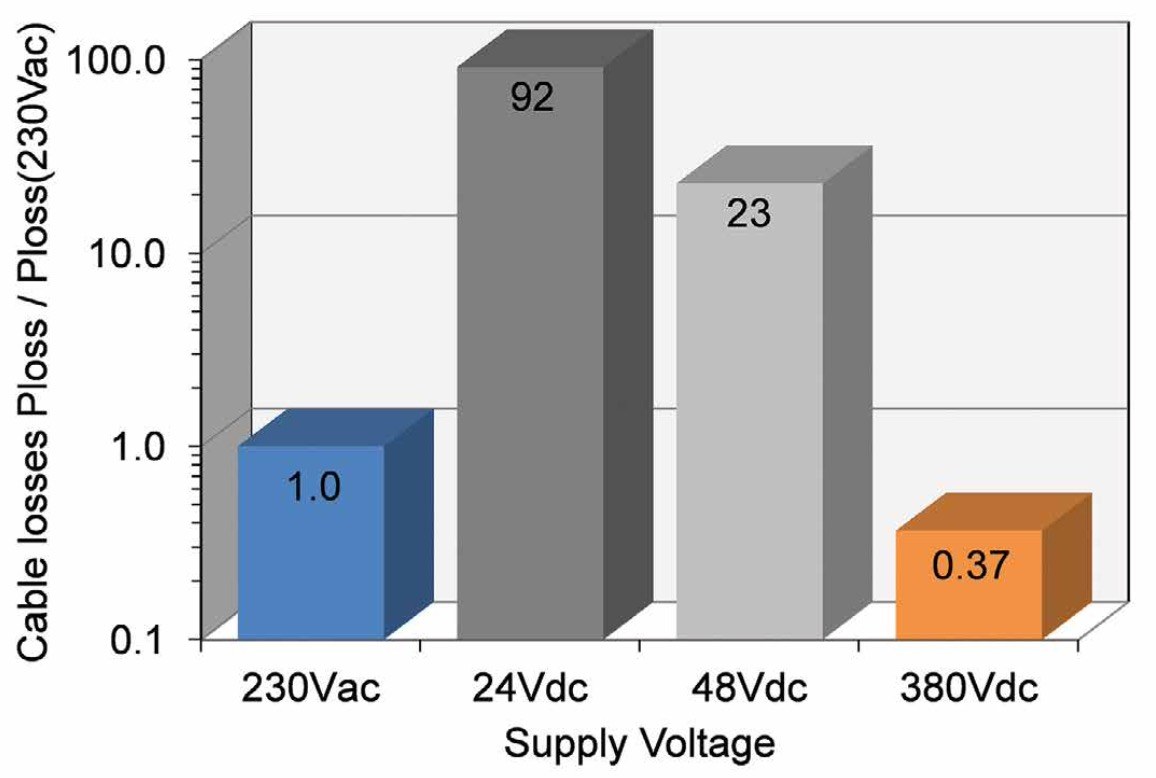
Figure 7: Comparison of cable losses for different supply systems. Losses are scaled to 230 VAC. Cable losses are equivalent to the amount of copper that is needed to achieve identical losses for the different voltages. Remark: 380 VDC requires similar insulation to 230 VAC
|
Organization |
Topic |
|
International Electrotechnical Commission (IEC) |
Many standards covering low voltage DC grid systems already |
|
SMB SG4 working group “LVDC distribution systems up to 1500V DC”: Managing new standardization projects at IEC technical committees (TC) |
|
|
National standardization working groups. Germany: TBINK-LVDC working group at DKE/VDE |
|
|
European Telecommunication Standardisation Institute (ETSI) |
European standard: EN 300 132-3-1 V2.1.1 (2012-02) |
|
Value: Definition of DC appliance inrush current limits and measurement setup |
|
|
EMerge Alliance |
Standardization working group on 380 V DC power grids for datacenters |
|
Standardization working group on 380 V DC for campus and microgrids |
This safety issue is discussed with other safety issues in more detail in reference [6]. It concludes that operating at a DC voltage of less than 380 VDC can be considered similar to operating at 230 VAC. A further safety aspect of DC grids discussed is arcing, which mainly appears when a load is unplugged during operation. Therefore, one must take care that lamps are not exchanged during operation in a DC system.
Standardization on
380 V DC
The voltage level of 380 V DC is not only attractive for lighting applications, but also for other applications like the power supply in data centers. A standardized DC supply system will produce the most advantages. Table 2 gives an overview of the organizations that work on standardization and their current work.
DC Lighting Demonstration Setup To demonstrate the functionality and to experience the problems related to it, a DC lighting demonstration is set-up in an office building at Philips Research in Eindhoven, The Netherlands.
Figure 8 shows a schematic overview of the system.

Figure 8: DC-grid demo installation with solar support and an AC reference grid. Grid voltage: 380 VDC, Solar modules: 2 kWpk, LED lamps: 56 x 37 W, adapted LED drivers, Reference system: 230 VAC
The DC part operates on 380 VDC and consists of a rectifier, a 2 kWpk photovoltaic (PV) generator and 54 LED lamps with 37 W each. The lamps are driven by lamp drivers, which are adapted to the DC system. Figure 9 shows photographs of the PV panels and of some of the lamps. The lamps illuminate the floor and are switched on during working hours throughout the day. In the best case, the PV generator is able to supply all the DC lamps. No feed in of PV power into the AC grid is provided.The lamps are Philips Xitanium lamps, with drivers modified for DC operation.
 Figure 9: Photos of the reference system: Photovoltaic panels (left), LED- Lamps (right)
A 230 V AC system is also in operation as a reference. Here, the PV power is directly fed into the mains grid. Furthermore, 18 comparable AC operated Xitanium LED lamps are monitored.
In the DC system the energy drawn from the mains grid is monitored. In the reference AC system, the energy needed by the lamps (including drivers) and the energy generated by the photovoltaic system (grid feed in) is monitored. To get a comparison, the needed lamp energy in the AC system is scaled to the number of lamps in the DC system. The generated PV energy in the AC system is scaled to the size of the DC PV system and finally both values are subtracted to achieve a net energy demand comparable to the DC system. Data was measured from April 29th, 2013 until Sept. 6th, 2013. The average power was calculated from the monitored energy. The results are shown for the DC power demand and the scaled AC power demand in figure 10. There are two gaps in the data resulting from failures and maintenance time, which are not considered for the final comparison. The figure shows that the power demand of the DC system is always lower than that of the comparable AC system. In total, the DC system demand was 2132.6 kWh, while 2181.4 kWh relate to the scaled AC system. In conclusion, the DC system energy demand was 2.24% lower than the comparable AC system.

Figure 10: Comparison of total consumption in the DC system and the AC reference system. The energy in the AC system is scaled to the DC system
Conclusion
Operating lamps and other devices with a residential DC grid offers two major benefits:
Overall power losses can be reduced. However, for a supply of the residential DC grid from a public AC grid, this effect is partly compensated by losses in the central rectifier. But energy savings become especially visible with the integration of additional local power sources.
As a further benefit, complexity can be reduced in the powered devices by shifting it into the infrastructure. This can make the devices more durable and reliable. Especially for mass products like lamp drivers and consumer devices, which are manufactured and used in a huge number, this will reduce the overall cost.
From a system point of view, it is advantageous to make those devices, which are needed in large numbers as simply and cheaply as possible and to allow a few central devices to be more complex. This cost advantage should be considered as the main benefit of the DC system.
The specification of a DC system should take these benefits into account: To reduce losses in the distribution system and the voltage should be as high as possible. For lamps, an operating voltage like 380 V DC is proposed.
To allow the reduction of complexity, the definition of a narrow voltage tolerance is required.
References
[1] Ulrich Boeke, Matthias Wendt, Lennart Yseboodt, "Combined Solar and AC Mains Powered LED Light-ing System", 14th European Conference on Power Electronics and Applications (EPE'11), Birminham, United Kingdom, 30.Aug.-1.Sept.2011.
[2] T.-F. Wu, Y.-K. Chen, G.-R. Yu, Y.-C. Chang, "Design and Development of DC-Distributed System with Grid Connection for Residential Applications", 8th International Conference on Power Electronics - ECCE Asia, May 30-June 3, 2011, The Shilla Jeju, Korea, paper no. TuF1-4.
[3] Rakwichian Wattanapong, “Community Smart Grid for ASEAN Decentralize Power”, Presentation at World Alternative Energy Forum, Chiang Mai, Thailand, 12.-14. Dec. 2012. (Online available (29.6.2014) at http://www.adicet.cmru.ac.th/waef2012/ )
[4] Bernhard Scheeren, “Optionen für eine Gleichstromversorgung in einem Wohnhaus“, Masterthesis at Cologne University of Applied Science, Institute for Electrical Power Engineering, Cologne, Germany and Zuyd Hogeschool, Heerlen, The Netherlands, 16. April 2014.
[5] Suponthana Wuthipong, „MW Scale Stand-Alone PV Hybrid Mini Grid System”, Presentation at World Alternative Energy Forum, Chiang Mai, Thailand, 12.-14. Dec. 2012. (Online available (29.6.2014) at http://www.adicet.cmru.ac.th/waef2012/ )
[6] Jung-Hoon Ahn, Dong-Hee Kim, Byoung-Kuk Lee, Hyun-Cheol Jin, Jae-Sun Shim, "DC Appliance Safety Standards Guideline through Comparative Analysis of AC and DC Supplied Home Appliances", Journal of Electrical Engineering & Technology Vol. 7, No. 1, 2012, pp. 51~57, Online available (29.6.2014) at: http://dx.doi.org/10.5370/JEET.2012.7.1.51
