Boost-Buck LED Driver Topology for Low Input and Output Ripple for Low EMI by Linear Technology
Many automotive LED driver circuits require constant-current DC/DC converter topologies that can both step-up and step-down the input-to-output voltage. Out of the commonly used step-up and step-down topologies, those that produce low EMI are the most desirable. Keith Szolusha, applications engineering section leader with Linear Technology, proposes a new boost-buck (boost-then-buck-mode) floating output LED driver to satisfy these requirements.
Automotive applications very often require constant-current DC/DC converters. To achieve a high efficiency, there are commonly four non-isolated LED driver topology options applied:
• Switch buck-boost for very high power and efficiency
• Coupled or uncoupled SEPIC
• Single inductor buck-boost mode
• Positive-to-negative (buck based) single inductor buck-boost
Unfortunately, none of these LED driver options has both a truly low input and low output ripple. Out of the need for such a converter, a new topology is created. The proposed new driver topology resembles the single inductor buck-boost mode, a single-switch-node SEPIC, and a positive version of a Cuk converter that also has low input and low output ripple. The topology features this low input ripple and low output ripple due to the input-facing and output-facing inductors (or coupled windings). The overall size of the combined boost-buck inductors (or coupled inductor) is similar to the single inductor of buck-boost mode. The input ripple is similar to a SEPIC, but the output ripple is much smaller. The inductor size is the same as a SEPIC, but with a single switch node instead of two (a smaller hot-loop) and without the complication of a coupling capacitor between the two windings. The input and output ripple resemble that of a low-input and low-output ripple (inverting) Cuk converter, but again, without the coupling capacitor between the windings and most importantly without the need for negative-referenced circuit feedback architecture. The positive boost-buck can be built with available boost LED drivers, such as the new LT3952 that is used in the first application example.
Boost-Buck Topology and Floating LED Output
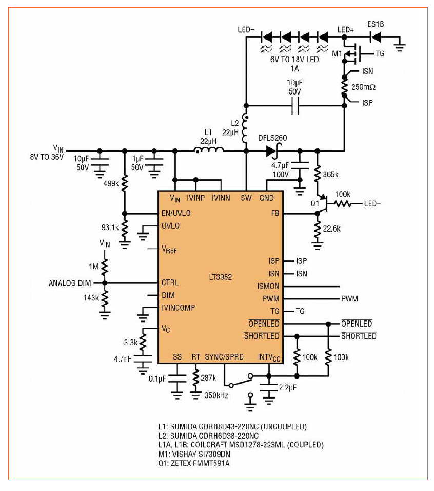
The new single switch 60 V monolithic LED driver IC with 4 A peak switch current can be used as an automotive boost-buck LED driver as shown in Figure 1. This 350 kHz, 1 A LED driver can power between 6 V and 18 V of LEDs from a 9 V to 36 V input with up to 90% efficiency at maximum load. The boost-buck converter efficiency is high due to the powerful internal MOS switch. The efficiencies with different LED string voltages are shown in figure 3. The versatile single, low-side power switch architecture can be used to power floating output step-up and step-down converters such as boost-buck and single inductor buck-boost mode. The LED string’s voltage reference to ground is not necessary since LED output is visible light only. Because of this, the unique floating LED driver topologies such as boost-buck and buck-boost mode are possible. Figure 1 (left): The 9-36 V 6 V to 18 VLED 1 A boost-buck LED driver has low input and low output ripple with 300:1 PWM dimming capability at 120 Hz and 90% efficiency
 Figure 2 (right): A single inductor buck-boost mode LED driver used for comparison to figure 1 boost-buck topology
This IC’s ability to PWM dim the floating LED string with the floating top gate ‘TG’ pin PWM MOSFET driver fits nicely with floating LED loads. The boost-buck in figure 1 can PWM dim at ratios of 300:1 and higher (with 120 Hz frequency).
The high-side TG driver effortlessly provides PWM dimming to boost, SEPIC, buck-boost mode, buck mode, and boost-buck LED drivers. It even doubles as a short-circuit protection disconnect to protect against the dreaded LED+-to-GND incident. The IC protects against and reports short-circuit and open LED conditions in boost-buck topology.
Boost-buck LED driver topology can both step-up and step-down the input-to-output voltage as it regulates the LED current. Boost-buck duty cycle, efficiency, switch current, and OUT node voltage are the same as both single inductor buck-boost mode and SEPIC.
Here are some properties of the boost-buck LED driver:
• VOUT = VIN + VLED
• DC = VLED / (VIN + VLED)
• Iswpk = IIN + ILED + ILpkpk / 2
• ILpkpk = IL1pkpk + IL2pkpk
• Efficiency of figure 1 is about 88% 12 VIN to 18 VLED at 1 A
 Figure 3: Boost-buck efficiency of figure 1 is as high as 90% with 12 VIN and 17.5 VLED 1 A LED string
Low Input and Output Ripple Topology Results in Low EMI
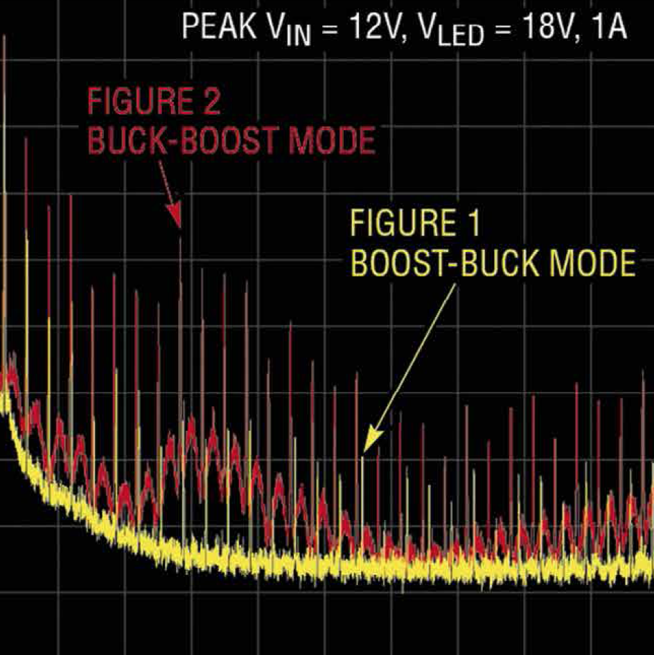
There are many similarities between boost-buck and single inductor buck-boost mode. What is not the same between figure 1 and figure 2 is the input and output ripple. Figures 4 a&b demonstrate the reduced conducted EMI of boost-buck versus buck-boost mode (Figure 1 and Figure 2 respectively). The separation of input and output windings prevents the output ripple current from coupling on the input capacitor of the boost-buck, thus reducing EMI. The EMI of Figure 4 shows low AM band EMI from 530 kHz to 1.8 Mhz and less of a need for a large EMI input filter.
 Figures 4 a&b: Figure 1 boost-buck conducted EMI (a) is much lower than figure 2 buck-boost mode conducted EMI (b) for 12 VIN, 18 VLED at 1 A
Figure 5 is an alternate drawing of the boost-buck topology, demonstrating the low in-and-out ripple paths in contrast to the SEPIC converter that does not have the same low output ripple. High ripple on either the input or output lines can radiate and increase EMI, especially if those lines are several meters long, as they sometimes are in a car. Additional LC filtering on the output of an LED driver is not recommended since it may inhibit optimal PWM dimming performance by slowing down PWM transitions and causing unwanted ringing. The low ripple, output-facing inductor yields the best combination of PWM dimming performance and low output EMI, like a buck. Note that the positive-to-negative single inductor buck-boost converter also has low output ripple and high bandwidth, but its input ripple and output ripple is notoriously coupled into large system input capacitance, creating larger than desired conducted EMI.
 Figure 5: Boost-buck LED driver is similar to SEPIC LED driver topology
Both the input and output capacitors in the boost-buck topology easily filter low triangular ripple current equal to
ILpkpk / sqrt(12)
A bit more capacitance or inductance can further reduce EMI in this topology. Neither the input or output capacitor is crucial in the converter’s high dI/dt hot-loop. In this topology, the critical hot-loop is constrained to the catch diode, OUT-to-GND capacitor, and the internal low-side switch, as indicated in figure 5, simplifying the layout. When the two inductors or windings of the boost-buck are tied together and the LED- node is connected to the input, the boost-buck is converter back to a previously-used buck-boost mode converter. In this scenario, the hot-loop currents and the input and output ripple currents can find their way onto the input and output capacitor alike, resulting in higher input and output ripple measurements.
 Figure 6: A 9-16 VIN, 18 VLED 3 A positive-to-negative boost-buck LED driver has low input and low output ripple and high 93% efficiency at 48 W LED
Alternate Boost-Mode- Then-Buck Positive-to- Negative Topology is Similar
Yet another patent-pending boost-buck LED driver topology with low-ripple input and output is shown in figure 6 using the LT3744. The positive-to-negative boost-buck (boost-mode-then-buck) is also a low input and low output ripple LED driver, but instead using a synchronous step-down converter with negative regulation capability. This new floating negative output topology takes advantage of the strengths of a synchronous step-down LED driver with PWM and output flag level-shift capabilities. Mainly, high efficiency is a major strength of a synchronous switching IC, especially when a high power LED string is driven such as the 3 A, 48 W LED load in figure 6. Synchronous step-up and down boost-buck LED drivers are possible with both synchronous boost and buck LED drivers.
Conclusion
The new, patent-pending boost-buck LED driver topologies provide step-up and step-down input to LED ratios with both low input ripple and output ripple. Appropriate LED drivers can be used for both simple and high power LED strings in automotive and industrial applications where high power and low noise are crucial without a sacrifice of PWM dimming performance.

